
Most rack‑related issues only surface after servers have been installed. Common pain points include rail kits with insufficient adjustment travel, rear doors pinching power cabling, or published 1,500 kg load ratings based on unrealistic test conditions.
A robust data‑center server‑rack specification begins with real‑world equipment requirements and site‑specific interfaces. Cabinet external dimensions should be determined only after analyzing chassis characteristics, rail kits, payload mapping, airflow behavior, cabling layout, floor constraints and maintenance workflows. This methodology gives sheet‑metal designers measurable requirements to work from.
At‑a‑glance key principles:
- Define your rack ecosystem first: 19‑inch Rack Unit (RU) and OCP Open Rack represent completely different mounting architectures.
- Create a payload map: total weight alone cannot describe rail reaction forces, center‑of‑gravity location or caster loading.
- Specify airflow by measured pressure drop: door open‑area percentage is not a valid cooling acceptance criterion.
- Separate bonding requirements from EMC requirements: a properly grounded metal rack is not automatically an RF‑shielded enclosure.
- Treat surface finish as part of joint design: powder coating improves durability but can also break electrical contact points.
2. Turn the IT Equipment List Into a Rack Specification
A server rack functions as a mechanical interface connecting IT hardware with facility infrastructure. Many costly rework events originate from selecting an off‑the‑shelf cabinet footprint and forcing servers, cables, cooling hardware and floor systems to adapt to it. A more reliable workflow locks in your full equipment matrix first, then traces every physical interface outward toward the cabinet structure.
Inputs worth locking before starting CAD work
| Input | What to capture | What it changes in the rack |
|---|---|---|
| IT equipment | Chassis envelope, weight, rail kit, handles, connector zones, service direction | Rail location, usable U‑space, front and rear clearance |
| Payload | Weight per U position, center of gravity, full‑ and partial‑population configurations | Uprights, base, crossmembers, casters, anchorage points |
| Air and liquid cooling | Air direction, expected flow rates, rear‑door heat‑exchanger or manifold interfaces | Door airflow resistance, blanking requirements, hose routing paths, rear service zone |
| Power and network | PDU (Power Distribution Unit) location, plug bodies, cable quantity, bend radius, overhead or under‑floor cable entry | Rack width, side cable channels, roof and base cutout openings |
| Site and installation | Floor‑loading capacity, seismic requirements, doorway dimensions, ramps, lifting equipment, raised‑tile layout | Overall cabinet envelope, shipping split design, leveling feet, casters, anchor mounting points |
| Maintenance | Door‑swing direction, replaceable components, hot‑swap service paths, locking and access policy | Hinge orientation, removable panel layout, aisle working clearance |
A 1 000 mm‑deep server installed inside a 1 200 mm cabinet can appear to offer ample clearance in simple 2‑D side‑view drawings. Real‑world space quickly shrinks once you account for front rail setback, rear power connectors, minimum cable‑bend radius, vertical PDUs and door internal structure. Always reference actual rail‑kit and connector geometry; nominal chassis depth alone does not represent the complete dimensional stack‑up.
Budget trade‑off: welded‑frame versus bolt‑together / knock‑down frame
A welded frame typically delivers direct load‑transfer paths and minimizes field‑assembly joints. Disadvantages include larger shipping volumes, tighter weld‑distortion management, and more complex field repair after physical damage. A bolted or knock‑down frame reduces freight footprint and simplifies on‑site component replacement. However, joint slip, fastener torque control, hole tolerance and assembly sequence all become critical structural design considerations. Neither construction method is inherently more dimensionally accurate. Final precision depends on production fixtures, datums, fastener specifications and formal test plans.
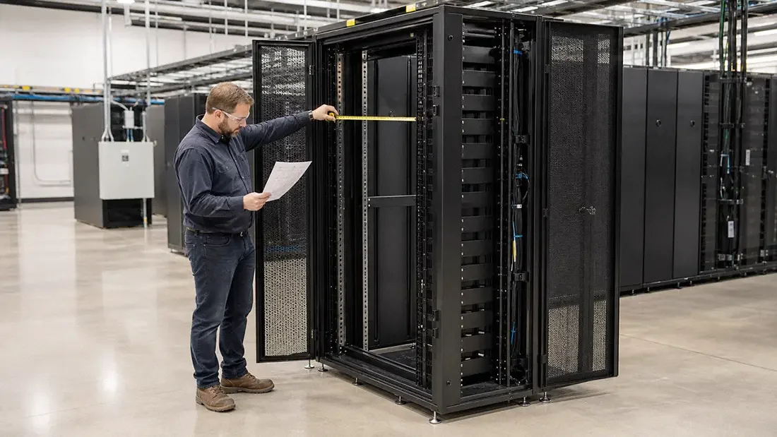
3. Mounting Interface & Service Clearances
The 482.6 mm (19‑inch) mounting series defined under IEC 60297 specifies only equipment mounting interface dimensions. It does not define cabinet outer width or depth. One rack unit (RU) measures 44.45 mm (1.750 in) in height. All surrounding factors including rail adjustment travel, door setback, side cable channels, cable‑management space and service‑access room must be explicitly documented on project drawings.
Square‑hole mounting rails with cage nuts are widely used to accommodate multiple server rail‑kit variants. Simply listing compatible hardware brand names is not sufficient acceptance criteria. Perform physical fit‑checks of left‑ and right‑hand rail assemblies at top, middle and bottom rack positions. Verify latch engagement, hardware insertion path, cable‑arm movement and component removal with doors mounted in their final installed state.
Build your dimensional stack‑up following this sequence
- Start with full chassis envelope including handles, front bezels, rear connector bodies and any attached rear cable‑management arms.
- Add rail‑kit adjustment range and required front‑to‑rear mounting‑plane separation distance.
- Add front‑side clearance for air intake, latches, handles and installed doors — do not calculate based only on bare frame dimensions.
- Add rear‑side clearance for connectors, minimum cable‑bend radii, PDUs, fluid manifolds and actual on‑site maintenance hand space.
- Verify facility entry‑route constraints including shipping crate dimensions, doorway widths, elevator capacity, floor loading, turning radius and whether racks ship fully populated with hardware.
Commonly‑discussed rack configurations include 42U, 45U and 48U heights; 600 mm (23.6 in) or 800 mm (31.5 in) widths; and 1 000 mm (39.4 in) or 1 200 mm (47.2 in) depths. These values serve only as starting reference envelopes, not hard compatibility rules. An 800 mm‑wide cabinet can deliver tangible value when side‑mounted PDUs or large fiber‑cable bundles would otherwise obstruct rear airflow paths.
Important: Do not mix rack ecosystems
OCP (Open Compute Project) Open Rack uses a 21‑inch equipment bay and 48 mm OpenU unit height. While Open Rack V3 supports standard 44.45 mm EIA rack units under specific pre‑configured settings, this capability does not make every ORV3 frame a drop‑in replacement for standard 19‑inch racks. Always explicitly specify base‑frame standard, adapter hardware, busbar assemblies, fluid manifolds and exact IT‑hardware mounting interfaces for your project.
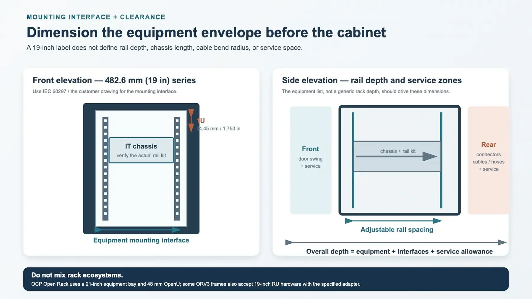
The mounting interface, rail depth, and service zones form one dimensional stack-up
4. Design the Load Path and Define Load Testing
A published static‑weight rating carries very limited engineering value without well‑defined load‑case conditions. A rack uniformly loaded with 1 200 kg distributed top‑to‑bottom behaves structurally very differently compared to the same total mass concentrated as four dense GPU trays mounted above the rack centerline. The high‑center‑gravity arrangement increases rail reaction loads, frame torsional twist, caster loading and tip‑over risk, even with identical overall scale weight.
Trace load transfer sequentially: equipment rail loads flow into mounting rails → upright columns → crossmembers → cabinet base → leveling feet or casters → finally onto the facility floor. Note that doors and side panels may add stiffness during supplier qualification testing. If those panels get routinely removed during on‑site service work, test articles must replicate that real‑world configuration. This same principle applies to aisle‑baying hardware and anchor‑bracket assemblies.
Separate operating, handling, shipping, and seismic load cases
- Operating static load: fully‑defined payload map, partial‑population scenarios, center‑of‑gravity location, cable and liquid‑system mass, foot‑or‑anchor support geometry.
- Installation and movement: caster reaction forces, floor threshold crossings, ramp travel, towing limits, door‑removal procedures; define whether racks move empty or fully populated.
- Shipping: pallet or skid support geometry, tie‑down mounting points, shock‑and‑vibration input profiles and exact shipped configuration state.
- Seismic and anchorage: site location, applicable building‑code requirements, floor‑system performance, anchor design criteria and requirements from the project structural engineer or AHJ (Authority Having Jurisdiction).
Multiple OCP‑qualified rack products advertise payload ratings near 1 400 kg, but this figure is not a universal default requirement for every AI‑computing rack. Each rating is product‑specific and tied to exact frame geometry, hardware configuration and documented test conditions. Request formal test reports or an agreed‑upon test procedure instead of copying maximum catalog numbers directly into purchase specifications.
Example supplier performance targets (require supporting context)
| Check | Possible starting target | Required context |
|---|---|---|
| Frame squareness | Diagonal difference ≤ 3 mm | Specify measurement height, reference faces and unloaded test condition |
| Front‑rail coplanarity | Coplanarity within 1 mm | Define datum reference, measurement gauge, rail positions and bolt‑torque values |
| Loaded frame deflection | ≤ 3 mm at defined reference points | Use approved payload map plus defined support boundary conditions |
| Static‑load hold test | Rated load maintained minimum 1 hour | Record pre‑load state, hold duration, ambient temperature and proof‑factor criteria |
| Functional post‑load check | Doors, latches, panels and rail‑kits operate correctly after loading | Repeat after unloading; document any permanent residual set or deformation |
When working within constrained budgets, add material thickness only along actual load‑transfer paths instead of thickening every sheet‑metal panel. Reinformed upright sections, base corner brackets, rail mounting brackets and caster support plates deliver higher return on investment compared to easily‑removable side covers. This strategy reduces overall weight and material expense, provided concentrated‑load and torsional load cases receive formal testing.
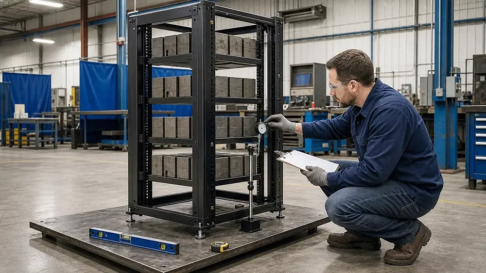
A useful load rating includes the payload map, test setup, and measured reference points
5. Treat Airflow as a Pressure‑Drop Problem
Door open‑area percentage represents purely geometric information; it cannot serve as a thermal acceptance metric. Two cabinet doors both quoted for 70 % open‑area can deliver significantly different pressure‑drop performance, driven by hole geometry, louver depth, inner skins, filter media, stiffener ribs, hinge hardware or multi‑layer door constructions. After rack delivery, real‑world installed conditions such as dense cable bundles and rear‑door heat‑exchanger hardware add further system‑level airflow resistance.
For front‑to‑rear cooled server racks, request measured pressure‑drop values across fully‑assembled front‑ and rear‑door assemblies at your project’s expected rack airflow rates. A performance curve measured across two‑to‑three distinct flow points delivers far more actionable data than a single static percentage value. Server‑fan performance curves plus facility static‑pressure conditions define real operating working points. Therefore allowable rack pressure‑drop limits should originate from your cooling‑system design rather than copied catalog specifications.
Control air recirculation before adding auxiliary rack fans
Install blanking panels to seal unused rack U‑height positions. Where feasible, block large bypass air gaps around mounting rails, cable penetrations and cabinet base openings while maintaining compliance with fire‑safety and cable‑routing requirements. Validate hot‑aisle / cold‑aisle orientation, door‑swing constraints, containment‑system interfaces and temperature‑sensor placement matching final populated‑rack hardware layouts.
A frequent engineering pitfall is adding top‑mounted auxiliary rack fans to compensate for poorly‑sealed or high‑restriction air paths. Depending on data‑center room layout these auxiliary fans can pull hot exhaust air backward toward server intakes or operate against native server‑fan pressure rise. Deploy auxiliary fans only when explicitly justified by airflow simulation and formal commissioning plans.
Acceptance‑record documentation checklist:
- Configuration: doors, filters, blanking panels, cable managers and heat‑exchangers must match hardware configuration used during testing.
- Airflow operating points: document minimum, nominal and maximum expected rack volumetric flow rates.
- Measurements: pressure‑drop across individual doors plus full assembled rack path; include location of all pressure‑tap measurement points.
- Integration validation: verify server inlet air temperatures and available fan operating margin under final equipment‑and‑cable installed state.
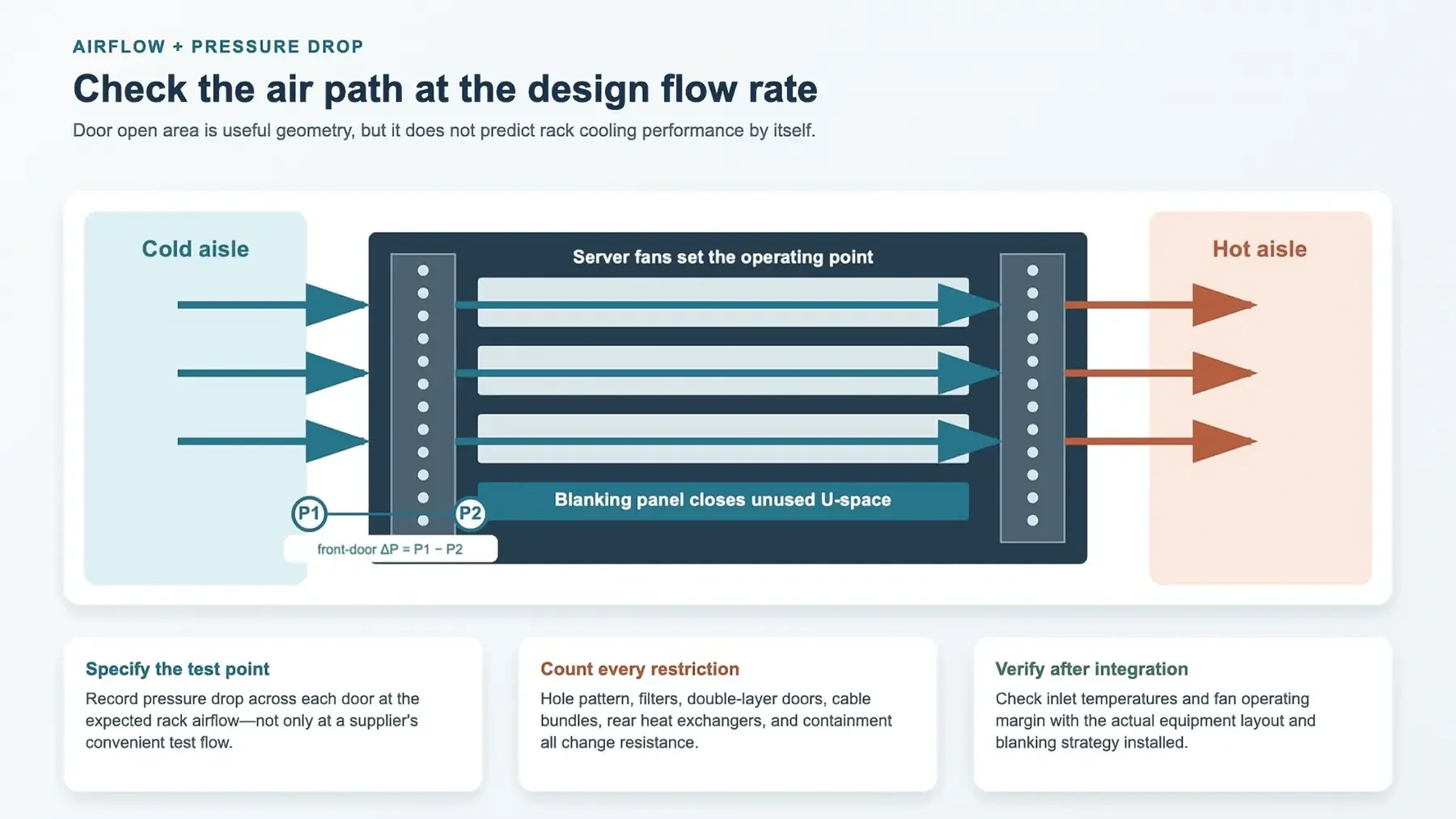
Measure the full air path at the expected rack flow rate
6. Sheet Metal, Joints and Finish as One System
For indoor powder‑coated server‑rack cabinets, ASTM A1008 cold‑rolled carbon steel serves as standard baseline material. ASTM A653 galvanized or galvannealed sheet can add extra corrosion resistance for selected sub‑components. Be aware that zinc‑based coatings impose special constraints for welding, surface pretreatment and edge‑touch‑up repair work. Stainless steel delivers benefits under aggressive environmental or cleaning‑chemistry conditions; within dry data‑hall environments it frequently adds significant material cost without solving core structural or thermal requirements.
| Rack component | Typical starting thickness range | Design note |
|---|---|---|
| Removable panels and door skins | 0.8–1.2 mm steel | Use returns, hems and perforation border features to minimize oil‑canning distortion |
| Formed uprights and crossmembers | 1.5–2.5 mm steel | Cross‑section geometry and joint spacing are as critical as raw material thickness |
| 19‑inch mounting rails | 2.0–2.5 mm steel | Verify cage‑nut fit, hole quality, rail twist and full‑height co‑planarity |
| Base and caster reinforcement plates | 2.5–4.0 mm local reinforcing plates | Dimension for concentrated reaction loads and real‑world support footprint geometry |
| Indoor powder‑coating system | 60–100 µm dry‑film thickness | This is a coating‑system reference range; drawing specifications and supplier datasheets govern final acceptance |
Weld‑procedure and fixture control outweigh automation
Resistance spot welding, short‑arc welding, rivets, clinch joints and bolted connections each have valid applications within rack fabrication. Robotic welding equipment can repeat poorly‑designed joints just as reliably as high‑quality ones. Fit‑up accuracy, fixture datums, joint access, heat‑input management, weld‑sequence planning and inspection protocols determine final frame squareness and mechanical performance. AWS D1.3 defines structural sheet‑steel welding requirements only when formally invoked within contract documents. Do not indiscriminately apply this specification to every spot‑weld or non‑structural tab feature. Explicitly mark which joints qualify as structural, define required welding‑procedure qualifications and specify inspection expectations. For production spot‑welds, document material stack‑up conditions, electrode access, weld spacing or count requirements plus destructive‑coupon or alternative process‑control verification matching project scope.
Coating acceptance criteria requires more than color‑chip approval
Powder‑coating real‑world performance depends upon cleaning, surface pretreatment, coating coverage, cure cycle, and base‑substrate material. Iron‑phosphate or zirconium‑based pretreatment systems work well for indoor steel racks; final process selection should be driven by coating‑supplier line‑capability data. Mask threaded features, sliding mating surfaces and bonding contact points prior to coating operations, rather than post‑production grinding back coating material.
ASTM D3359 defines tape‑adhesion test classification grades but cannot deliver absolute bond‑strength values. Projects may select acceptance grades of 4B or 5B, but test methodology, dry‑film thickness range, substrate preparation, tape selection, pre‑test conditioning and operator controls must all be documented. Measure dry‑film thickness using calibrated gauges following ASTM D7091 or mutually‑agreed equivalent procedure.
Standard ventilated server racks are not hermetic environmental enclosures. When NEMA‑type or IEC 60529 IP‑rating compliance is required, you must specify and test the complete fully‑assembled enclosure, inclusive of doors, fan panels, cable penetrations, gaskets and all field‑installed accessories. NEMA enclosure ratings and IEC IP ratings are not one‑to‑one interchangeable specifications.
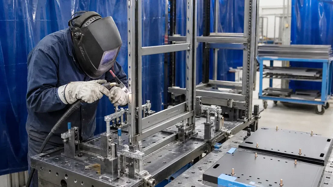
Joint fit-up and fixture control matter more than whether the torch is manual or robotic
7. Bonding, EMC and Cable Entry Requirements
ANSI/TIA‑607‑E covers telecommunications protective bonding and grounding infrastructure and its interconnection with building systems. This standard does not establish one universal resistance‑limit value applicable to every server‑rack design. If electrical continuity becomes an acceptance test item, fully define test‑point locations, measuring‑instrument requirements, lead‑wire compensation, test current magnitude, contact‑pressure conditions and maximum acceptable measured value. Four‑wire low‑resistance measurement methods are appropriate for very‑low‑resistance targets; selection should be made by the project design engineer.
Install dedicated bonding studs or pre‑prepared bare‑metal contact zones on main frame members, hinged doors and removable panels where bonding continuity is required. Mask these defined contact surfaces before powder‑coating. Specify approved hardware for bonding jumpers, and route jumpers to avoid binding or tensioning across full door‑swing travel. Serrated lock‑washers can help break through surface films, yet they are no replacement for controlled bare‑metal contact surfaces plus repeatable assembly procedures.
Cable‑entry zones need complete drawing details: usable clear opening after edge‑protection treatments, minimum cable‑bend radii, strain‑relief provisions, power‑vs‑data‑cable separation requirements, brush‑or‑gland sealing hardware, plus maintainable routing paths navigating around PDUs and fluid manifolds. Large late‑program cutouts can weaken cabinet roof or base structures while creating sharp‑edged, congested maintenance zones.
Important distinction: Grounded ≠ RF‑shielded enclosure
Most data‑center IT equipment satisfies regulatory EMC requirements at the individual hardware unit level. A conventional server‑rack cabinet fitted with heavily perforated doors and large cable‑entry cutouts cannot be casually described as delivering 40 dB RF attenuation without purpose‑built enclosure engineering plus formal qualification testing. When RF‑shielding performance becomes a requirement, agree upon operating‑frequency range, pass‑fail attenuation criteria, formal test‑method documents, cable‑feedthrough hardware, ventilation‑panel specifications, door‑seam gasketing and exact test‑article configuration.
Shielding performance and cooling performance frequently impose conflicting design constraints. Conductive mesh screens, honeycomb ventilation panels, finger‑stock gaskets and filtered cable feed‑throughs all add airflow pressure‑drop, hardware cost and ongoing maintenance overhead. These trade‑offs must be evaluated at full‑system level and cannot be hidden behind a generic “EMC‑rated rack” specification note.
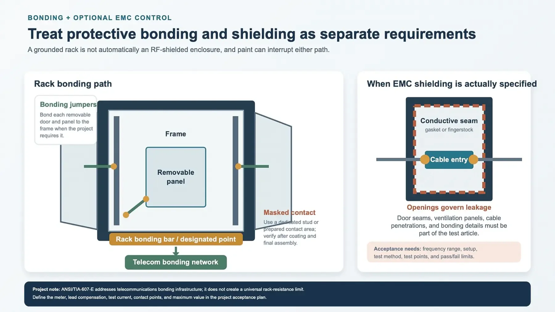
Protective bonding and optional EMC shielding need separate acceptance requirements
8. High‑Density AI and Liquid‑Cooled Rack Interfaces
There exists no fixed universal kW threshold at which air‑cooling instantly becomes impractical. Real‑world cooling limits are determined by server hardware design, allowable equipment‑inlet air conditions, facility airflow capacity, server‑fan power budget, hot‑aisle containment, site altitude and heat‑rejection‑system architecture. ASHRAE guidance for AI‑focused data‑centers discusses liquid‑assisted cooling architectures starting around 60‑120 kW per rack as an industry trend indicator; these values serve for orientation only and cannot replace project‑specific thermal simulation work.
Even direct‑to‑chip liquid‑cooled hardware still rejects residual heat via air from internal power supplies, memory modules, storage and networking components. Therefore liquid‑cooled racks frequently need both liquid‑fluid interfaces and conventional air‑handling provisions. Rear‑door heat‑exchanger assemblies add hinge‑system loads, hose‑movement constraints and additional rear‑side service‑depth requirements. Immersion‑cooled hardware represents a fundamentally distinct enclosure architecture rather than a standard server‑rack with a small set of added fluid fittings.
Add liquid‑system requirements to your mechanical‑interface checklist
| Interface | Questions to resolve before rack release | Sheet‑metal / cabinet impact |
|---|---|---|
| Manifold assembly | Side‑mount or rear‑mount; supply‑return orientation; isolation provisions; service‑removal capability | Mounting brackets, frame stiffness requirements, clearance zones, bonding provisions |
| Quick‑disconnect couplings | Mating‑force magnitude; dripless‑type requirement; physical access; keying; service‑change‑out procedure | Local structural reinforcement, hand‑working clearance, protective guards |
| Cooling hoses | Minimum bend‑radius, dynamic motion, abrasion protection, hot‑swap routing, labeling requirements | Routing channels, edge‑protection features, door‑and‑rail interference clearance |
| CDU and facility piping | In‑rack versus row‑level CDU placement; service mass, vibration isolation, utility connection layout | Payload‑map updates, base‑reaction‑load analysis, rear‑and‑side‑envelope sizing |
| Leak‑detection hardware | Sensor‑cable routing, drip‑collection path, alarm‑signal interfaces, visual inspection‑access | Base‑tray geometry, drainage strategy, removable‑cover provisions |
| Condensation‑control strategy | Fluid operating‑temperature range, dew‑point margins, insulation specifications, system‑shutdown response logic | Clearance for insulated pipe runs and sensor‑mounting locations |
If implementing an Open Rack V3 platform, reference official OCP base‑frame, IT‑hardware, power‑busbar and blind‑mate manifold specifications directly; avoid manually translating requirements into generic 19‑inch cabinet wording. When staying with 19‑inch architecture, confirm physical coexistence between GPU rail‑kits, fluid manifolds, cable‑management arms and service tools within final cabinet depth.
Rack‑manufacturers take ownership for frame‑structure and integration items under their direct control. Pressure‑testing, fluid‑chemistry control, valve‑qualification, system flushing and leak‑acceptance testing frequently fall under cooling‑system‑supplier responsibility. Explicitly document responsibility boundaries inside acceptance‑planning documents. A passing cabinet‑inspection result does not automatically validate untested liquid‑cooling loop performance.
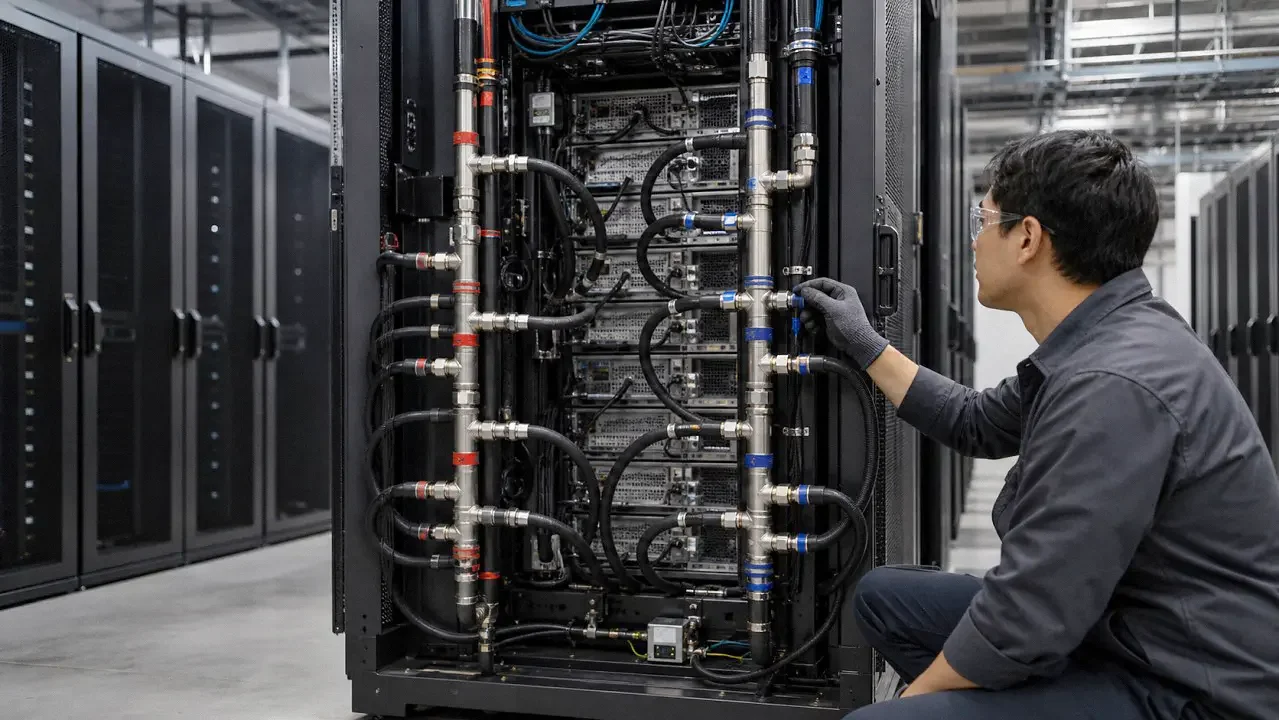
Liquid cooling adds manifold, hose, leak-detection, and service interfaces to the rack
9. Use Rack Specification as a Technical Interface
A reliable data‑center server‑rack cannot be defined purely by maximum RU height, highest published load rating or single door‑open‑area percentage. True quality originates from mutually‑compatible physical interfaces plus acceptance‑test plans that replicate real operating conditions your cabinet will encounter in service.
Start specification work from equipment‑list and service‑access requirements. Separate operating, shipping and seismic load‑case definitions. Characterize cooling performance by measured pressure‑drop rather than simple geometry. Write bonding, EMC shielding, surface‑finish and liquid‑cooling requirements as independent specification sections. This approach gives fabricators clear measurable targets while still permitting reasonable trade‑offs across material selection, joint‑design and overall project cost.
Concise release‑package documentation checklist:
- Mechanical: rack ecosystem definition, full equipment matrix, rail‑kit requirements, dimensional stack‑up, payload map, support boundary‑conditions and service‑clearance geometry.
- Thermal: airflow direction and operating flow‑points, allowable pressure‑drop budget, blanking‑panel strategy, containment interfaces plus liquid‑cooling hardware specifications if applicable.
- Electrical: bonding‑point layout plus test‑method definition, cable‑entry geometry, PDU mounting layout and any project‑specific EMC‑shielding requirements.
- Manufacturing: material grades and thickness values, joint‑design notes, complete coating‑system requirements, masked contact zones, cosmetic‑surface definitions and production‑inspection criteria.
- Verification: defined load‑test and functional‑test protocols, dimensional‑report deliverables, coating‑quality records, bonding‑continuity results and configuration‑controlled reference photographs.
FAQ
Final Summary
Successful data‑center server‑rack design is driven by system‑level interfaces rather than isolated catalog parameters. Define IT‑hardware requirements first, then derive cabinet dimensions, loading requirements, cooling constraints, bonding rules and liquid‑system interfaces outward from equipment needs. Always define formal acceptance‑test conditions replicating real‑world service configurations.
Avoid relying only on marketing‑sheet figures for load‑capacity or airflow performance. Document complete mechanical, thermal, electrical, manufacturing and verification deliverables inside your release package. This workflow reduces costly rework and misinterpretation between design, procurement, fabricator and on‑site installation teams.
Engineering note: All numerical values inside this article serve only as starting‑point guidance. They cannot replace project‑specific engineering evaluation. Operating environment, mechanical loads, cooling requirements, local building‑codes and customer contract requirements may demand completely different cabinet specifications.
Technical References
This article references the industry standards and guidance documents listed below. Project documentation must reference the exact revision required per contract, customer or certification‑program requirements. No external hyperlinks are provided; many official standards documents require separate purchase.
- IEC 60297‑3‑100 — Basic dimensions for the 482.6 mm (19‑inch) series of racks and cabinets
- Open Compute Project — Open Rack specifications, ORV3 base‑frame, IT‑gear, power and manifold documentation
- ANSI/TIA‑607‑E — Telecommunications bonding and grounding infrastructure
- ANSI/TIA‑942‑C — Telecommunications‑infrastructure standard for data‑center facilities
- ASHRAE AI Data Center Energy and Thermal Efficiency — Cooling‑architecture guidance for high‑density AI facilities
- AWS D1.3/D1.3M:2025 — Structural welding‑code for sheet‑steel applications
- ASTM D3359‑23 — Tape‑test classification for organic‑coating adhesion
- ASTM D7091‑22 — Non‑destructive dry‑film thickness‑measurement for applied coatings
- ANSI/NEMA 250‑2020 — Enclosure‑type requirements and scope‑of‑application notes
- UL data‑center standards overview including UL 2416 rack‑system and UL 2416A immersion‑cooling‑cabinet requirements