
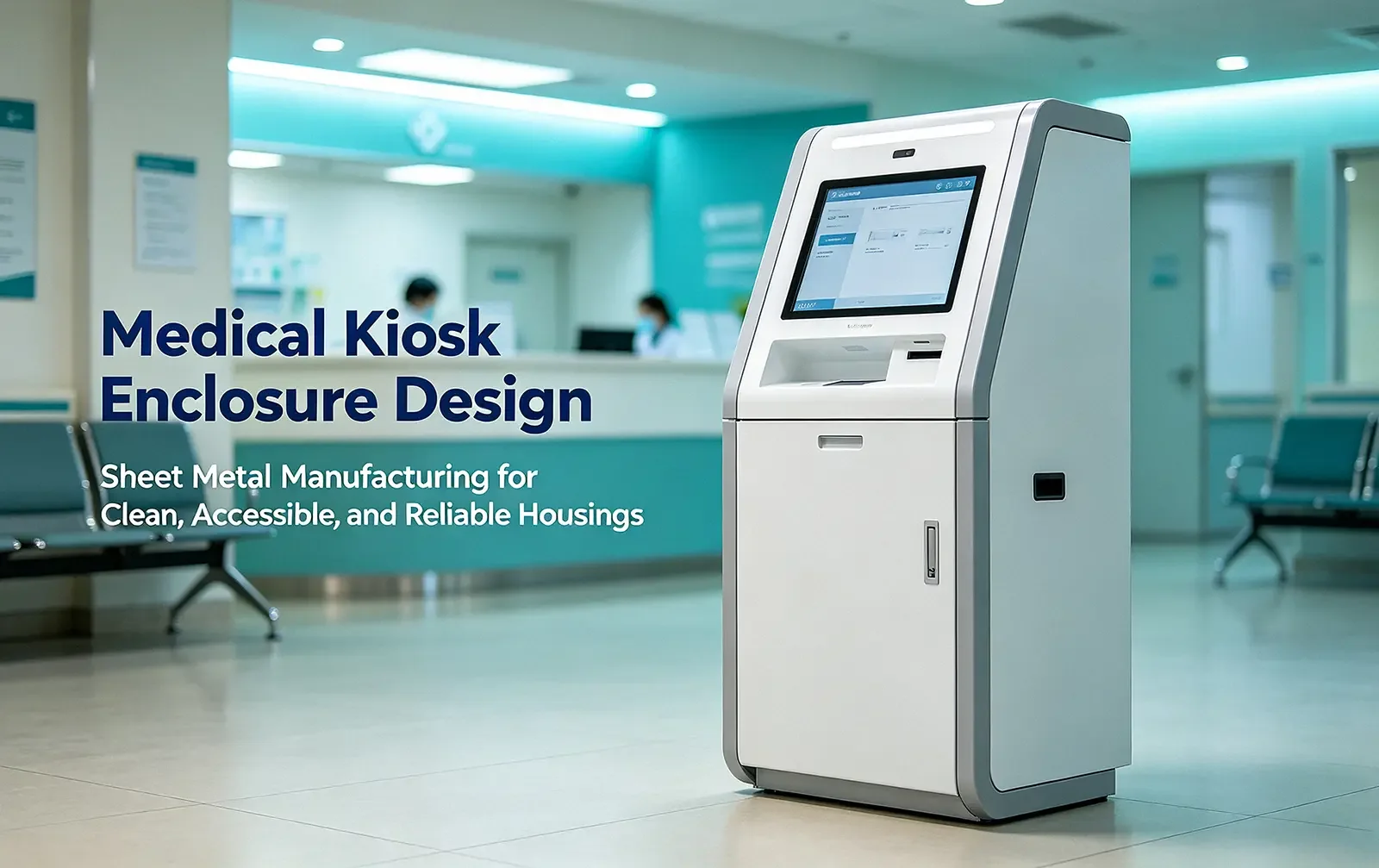
A kiosk can look clean in a rendering and still become a maintenance problem after its first month in a hospital. The failures usually show up at seams, touch surfaces, service doors, and cable entries—not in the broad flat panels that get most of the design attention.
A medical kiosk enclosure has to support routine cleaning, public use, field service, electronics cooling, and an accessibility plan at the same time. In our experience, the design is more reliable when those operating conditions are defined before anyone chooses a metal grade or starts detailing bends. The sections below describe a practical way to make those decisions without treating stainless steel, a heavy gauge, or a particular coating as a universal answer.
1. Start with how the medical kiosk will actually be used
The first design review should be about the use case, not the metal. A check-in terminal in a dry outpatient lobby sees a different cleaning schedule and abuse level than a payment kiosk near an emergency department entrance. A report-printing station may need daily paper access, while a wayfinding kiosk may stay closed for months.
A common pitfall we see is a requirement such as “hospital-grade enclosure” with no definition behind it. That phrase does not tell the fabricator which disinfectants are used, whether staff spray or wipe, how often the printer door opens, whether the kiosk is anchored, or whether the electronics are medical electrical equipment. Those details change the enclosure.
Separate administrative kiosks from medical electrical equipment
Separate administrative kiosks from medical electrical equipment
Many registration, payment, and document kiosks function as information and communications technology equipment. UL 62368-1 may be a relevant product-safety route for that type of equipment. IEC 60601-1 applies to the basic safety and essential performance of medical electrical equipment and medical electrical systems; it should not be added automatically just because the kiosk sits in a hospital.
If the kiosk performs a medical function, connects to applied parts, or becomes part of a medical electrical system, the 60601 series may become relevant, including EMC requirements under IEC 60601-1-2. Make that classification decision with the regulatory team or NRTL before the sheet-metal architecture is frozen. It affects spacings, protective earth, access to hazardous parts, labeling, power entry, and test access.
Convert the cleaning and service workflow into inputs
Ask the facility or product owner for the cleaning SOP and the list of approved products. CDC guidance for noncritical equipment emphasizes manufacturer instructions and material compatibility. That is more useful than assuming every hospital wipes with the same alcohol or bleach concentration.
- Cleaning: product name or chemistry, concentration, wet contact time, wipe material, daily frequency, and whether residue is rinsed.
- Service: paper refill frequency, filter interval, expected module replacement, tools allowed, and whether service occurs in a public area.
- Environment: indoor temperature range, dust load, humidity, likely spills, proximity to entrances, and any requirement for a NEMA or IP enclosure rating.
- User interaction: screen, card reader, scanner, printer slot, bag shelf, privacy needs, reach approach, and expected impact or leaning loads.

2. Choose sheet metal and finish as one system
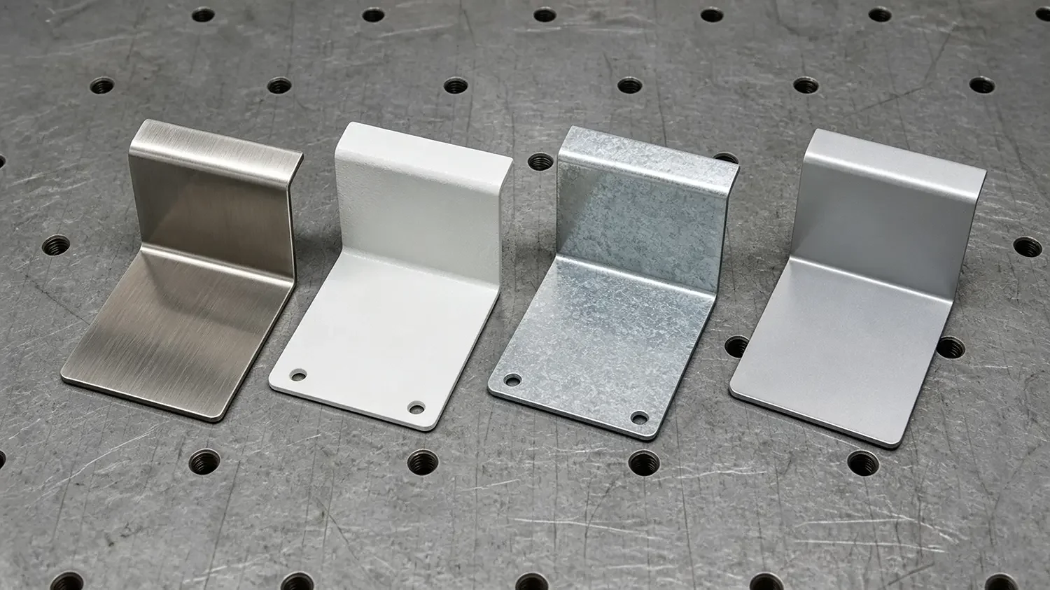
There is no single default material for a medical kiosk enclosure. Stainless steel reduces dependence on an organic coating, but it costs more to buy and fabricate. Powder-coated carbon steel can perform well indoors when the pretreatment, edge design, and cleaning chemistry are controlled. Aluminum reduces weight, but its lower stiffness changes panel thickness and reinforcement.
The table below gives practical starting ranges, not final structural values. Panel span, anchorage, expected impact, hinge loads, and internal brackets still need calculation or prototype testing. On drawings, specify decimal thickness as well as gauge; gauge numbers do not map to one thickness across all metals.
|
Material |
Practical starting thickness |
Where it fits |
Tradeoffs to manage |
|
ASTM A1008 CS Type B carbon steel |
Frame/base: 14–16 ga (0.075–0.060 in; 1.9–1.5 mm). Skins: 16–18 ga (0.060–0.048 in; 1.5–1.2 mm). |
Good stiffness per dollar; easy to weld; common for internal chassis and lobby-only outer panels. |
Needs disciplined pretreatment and a continuous coating. Scratches and cut edges can expose steel. |
|
ASTM A653 galvanized sheet |
Often 16–20 ga; specify decimal thickness and coating designation on the drawing. |
Useful where the chassis may see occasional humidity or condensation; often used for internal trays. |
Welding burns zinc locally; fumes, coating repair, cut-edge protection, and powder adhesion need a process plan. |
|
5052-H32 aluminum to ASTM B209 |
Common enclosure starting range: 0.080–0.125 in (2.0–3.2 mm), depending on panel span and stiffening. |
Lower weight, good corrosion resistance, and better bending behavior than 6061-T6 for formed housings. |
Lower elastic modulus can require thicker panels or formed ribs. Isolate aluminum from dissimilar metals in wet areas. |
|
304L or 316L stainless to ASTM A240 |
Outer panels and doors commonly start at 16–20 ga (about 0.060–0.036 in; 1.5–0.9 mm). |
Uncoated cleanable surface; useful for touch zones and locations where coating damage is hard to tolerate. |
Higher material and fabrication cost. 316L offers more chloride resistance, but neither grade is immune to poor chemistry or trapped residue. |
Match the finish to the substrate and cleaning chemistry
For a coated carbon-steel housing, a common indoor starting specification is zinc-phosphate or equivalent pretreatment followed by a polyester powder coat around 2–3 mil (50–75 μm) dry-film thickness. That range is not a substitute for the powder supplier’s technical data sheet. Complex corners, welded zones, and Faraday-cage areas need the same attention as the easy flat surfaces.
For stainless, decide whether the appearance should be 2B, a directional No. 4 brush, or another controlled finish. Keep grain direction consistent on adjacent panels, protect finished surfaces during fabrication, and clean weld heat tint using a qualified stainless process. An anti-fingerprint topcoat can reduce visible oils, but it still has to survive the selected disinfectants.
We would treat “antimicrobial coating” as a separate regulatory and validation discussion, not as a hygiene shortcut. EPA guidance distinguishes coatings that protect the article itself from products making public-health claims. Either way, the surface still needs a documented cleaning method.
Two selection tradeoffs that come up in real projects
Budget-limited outpatient lobby. For a dry, supervised lobby with wipe-only cleaning, an ASTM A1008 carbon-steel frame and outer skins can be a reasonable cost choice. Put the money into surface preparation, a qualified powder system, clean panel returns, and replaceable high-touch pieces. A stainless touchscreen bezel or kick plate can localize wear without making the entire chassis stainless.
High-touch location with aggressive chemistry. If cleaning is frequent and coating damage would be difficult to manage, 304L stainless on the exposed shell with a coated-steel internal chassis may reduce finish risk. Move to 316L only when chloride exposure, residue, or corrosion testing supports the added cost. The material change does not remove the need to test seals, labels, adhesives, and the display stack.
3. Design the enclosure around the cleaning path
Cleanability is mostly a geometry problem. A smooth finish helps, but the person wiping the kiosk still has to reach the surface, keep it wet for the product’s contact time, and remove soil from transitions. Decorative grooves, upward-facing lap seams, exposed foam tape, and deep recesses make that work harder.
Use formed returns and controlled joints
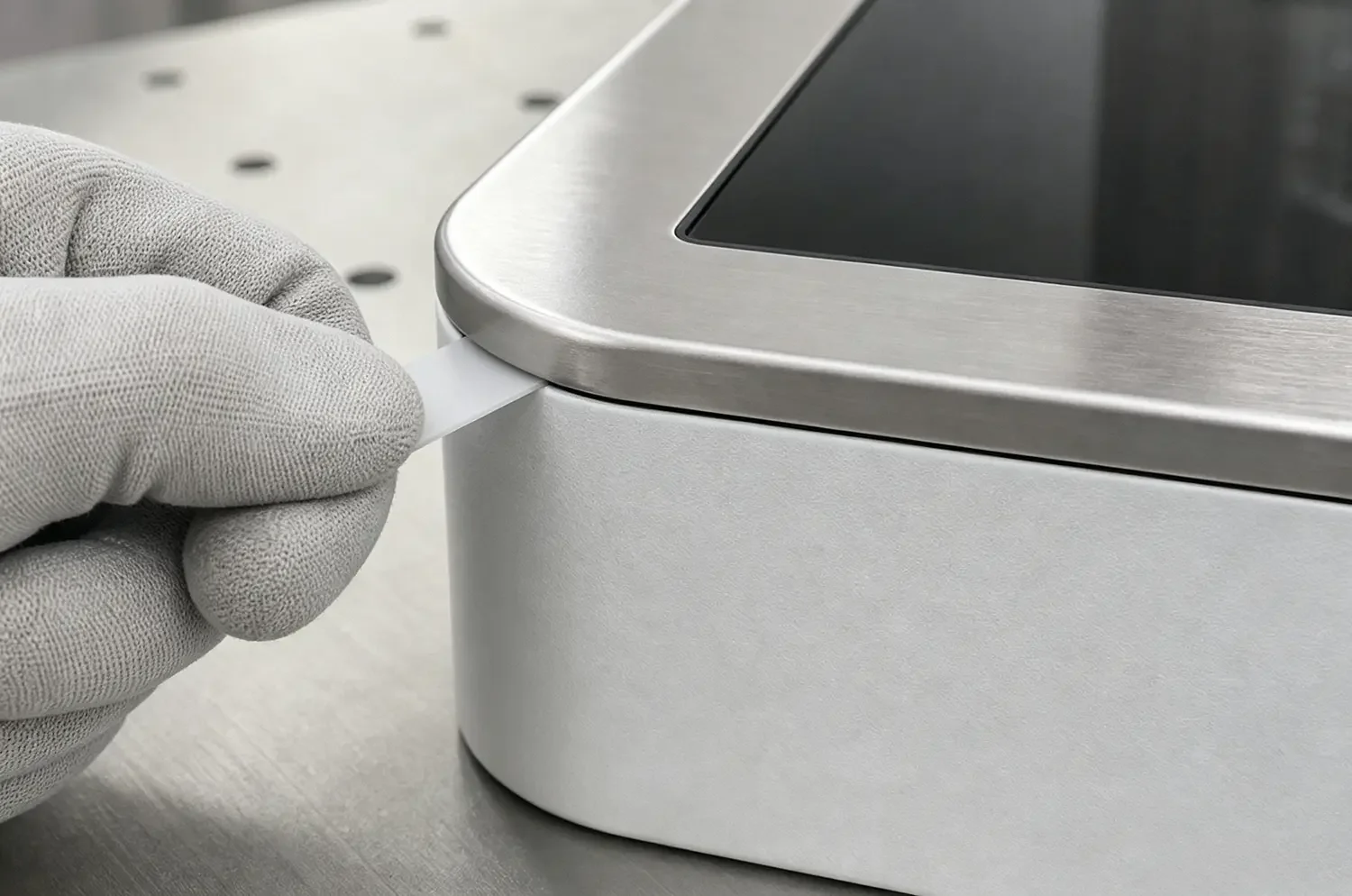
At user-facing edges, use hems or returned flanges to remove sharp edges and add stiffness. External corners should have a radius that a wipe can follow without snagging. Where two panels meet, decide whether the joint is a cosmetic gap, a service joint with a gasket, or a sealed liquid barrier. A nominal gap by itself is not an infection-control feature.
For a visible service door, a 0.060–0.100 in (1.5–2.5 mm) gap is a workable prototype starting point if the variation stays controlled. A sealed splash zone needs a continuous, chemically compatible gasket or sealant and an ingress test. Concealed fasteners usually make the wipe path easier, while captive fasteners make service hardware less likely to disappear.
Test the actual disinfectant exposure
An arbitrary 500-wipe test can create false confidence. At ten cleanings per day, 500 cycles represent only 50 days. Start with the expected cleaning frequency and service life, then build a test matrix using the actual product concentration, wet contact time, wipe material, temperature, and any rinse step.
Inspect more than color. A useful compatibility review checks gloss change, color difference, softening, cracking, coating adhesion, seal swelling, label legibility, adhesive creep, screen haze, and corrosion at scribed or cut edges. Include assembled seams and mixed-material joints, not just flat witness panels.
In our experience, this is also the right time to simplify the industrial design. If a groove, badge recess, or trim ring adds a cleaning step without helping service or structure, it usually does not earn its place on a patient-facing kiosk.
4. Build the structure for service, heat, and electrical safety
Thicker sheet is not the only way to make an enclosure feel solid. Returns, hat channels, local doublers, door geometry, and attachment spacing often add stiffness with less weight. An 18-gauge skin with useful formed depth can outperform a heavier flat panel that drums or twists.
Keep routine service away from powered electronics
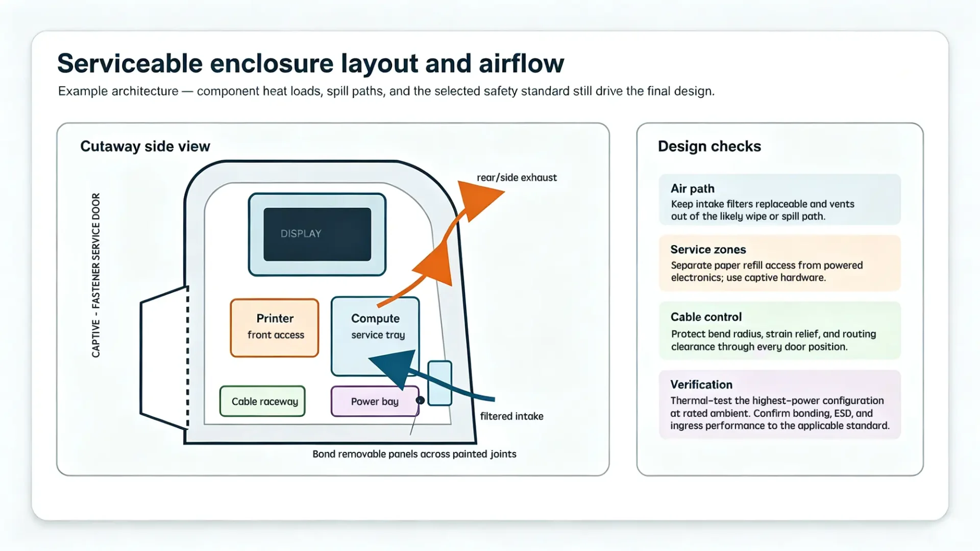
Give the printer or consumable compartment its own access whenever the product layout allows it. Paper refill should not expose line-voltage terminals, loose harnesses, or the compute module. Use captive screws or quarter-turn hardware where repeated service is expected, and verify that every door can open without pulling a cable below its bend radius.
Internal cable routing needs defined tie points, strain relief at the power entry, abrasion protection at pass-throughs, and clearance from fans, hinges, and hot components. Self-clinching hardware is useful, but minimum sheet thickness, edge distance, installation force, torque, and push-out capacity should follow the fastener supplier’s data and be checked on production material.
Design airflow around spills and maintenance
Lower intake and upper rear or side exhaust is a common arrangement, not a rule. Keep intake openings away from mop splash and avoid placing an unprotected vent on a horizontal surface that gets wiped. Filters should be replaceable without a full teardown and keyed so they cannot be installed backward.
Build the thermal model from component power, fan curve, filter pressure drop, vent free area, and rated ambient. Then verify the highest-power configuration with thermocouples in the assembled enclosure. A partially loaded filter or a failed fan can be a more useful margin case than a clean-room bench test.
Let the selected safety standard set bonding and ESD tests
Bond doors and removable metal panels across painted joints using a defined bare-metal interface, bonding strap, or qualified fastener stack. Masked bond areas need corrosion protection that does not defeat electrical contact. Avoid writing a universal 0.1-ohm requirement into the enclosure drawing; protective-bonding test current, duration, and acceptance come from the applicable product standard.
Touchscreens, card readers, and metal bezels also create ESD entry points. IEC 61000-4-2 defines ESD immunity test methods, while medical electrical equipment may be evaluated through IEC 60601-1-2. If an ingress rating is required, test the assembled product to the chosen NEMA 250 or IEC 60529 classification. NEMA Type and IP ratings are related but not interchangeable labels.
5. Set accessibility dimensions from the installed approach
A fixed “accessible control height” is not enough. The kiosk base, counter depth, card-reader projection, clear floor area, and the user’s approach all interact. Start with the installed configuration and check every operable part—not only the center of the touchscreen.
Under the 2010 ADA Standards, clear floor space is at least 30 by 48 in (760 by 1220 mm). For an unobstructed forward or side reach, operable parts fall between 15 and 48 in (380 and 1220 mm) above the floor. An obstructed forward reach is different: the maximum remains 48 in when reach depth is no more than 20 in, but drops to 44 in when the reach is deeper than 20 in and no more than 25 in.
Operable parts should work with one hand, without tight grasping, pinching, or wrist twisting, and with no more than 5 lbf (22.2 N) activation force. If the design relies on knee and toe clearance for a forward approach, Section 306 adds its own depth, height, and 30 in minimum width requirements.
Prototype with both seated and standing users. Check screen glare and viewing angle, the reach to the highest on-screen target, card insertion, receipt pickup, scanner aiming, and whether an open service or printer door intrudes into the accessible route. A common pitfall we see is a touchscreen placed correctly while the receipt slot or payment terminal ends up outside the usable reach range.
6. Put measurable requirements on the drawing and inspection plan
The drawing should tell the fabricator what matters to function and what can float. When every dimension carries a tight block tolerance, cost rises without improving the kiosk. When visible gaps, screen alignment, hinge datums, or bond locations are left undefined, assembly becomes an interpretation exercise.
Use prototype values as a starting point, not a hidden standard
The values below are reasonable discussion points for a medium-size floor-standing kiosk. They are not universal industry requirements. Confirm them against the display, reader, gasket, hinge, coating, and supplier process before release.
|
Feature |
Prototype starting point |
Engineering note |
|
Visible door gap |
0.060–0.100 in (1.5–2.5 mm) |
Control uniformity along the edge to about 0.020 in (0.5 mm); change the target if a gasket or ingress rating drives it. |
|
User-facing panel flushness |
0.020–0.040 in (0.5–1.0 mm) |
Measure in the assembled condition, including gasket compression and hardware stack-up. |
|
Critical display or reader cutout |
±0.020 in (±0.5 mm) from functional datums |
Use profile or true position when the interface has multiple related holes; confirm the tolerance with the supplier. |
|
Powder-coat dry-film thickness |
2–3 mil (50–75 μm) as a common starting range |
The powder supplier’s data sheet and the corrosion/appearance requirement govern the final range. |
Specify the full finish and assembly condition
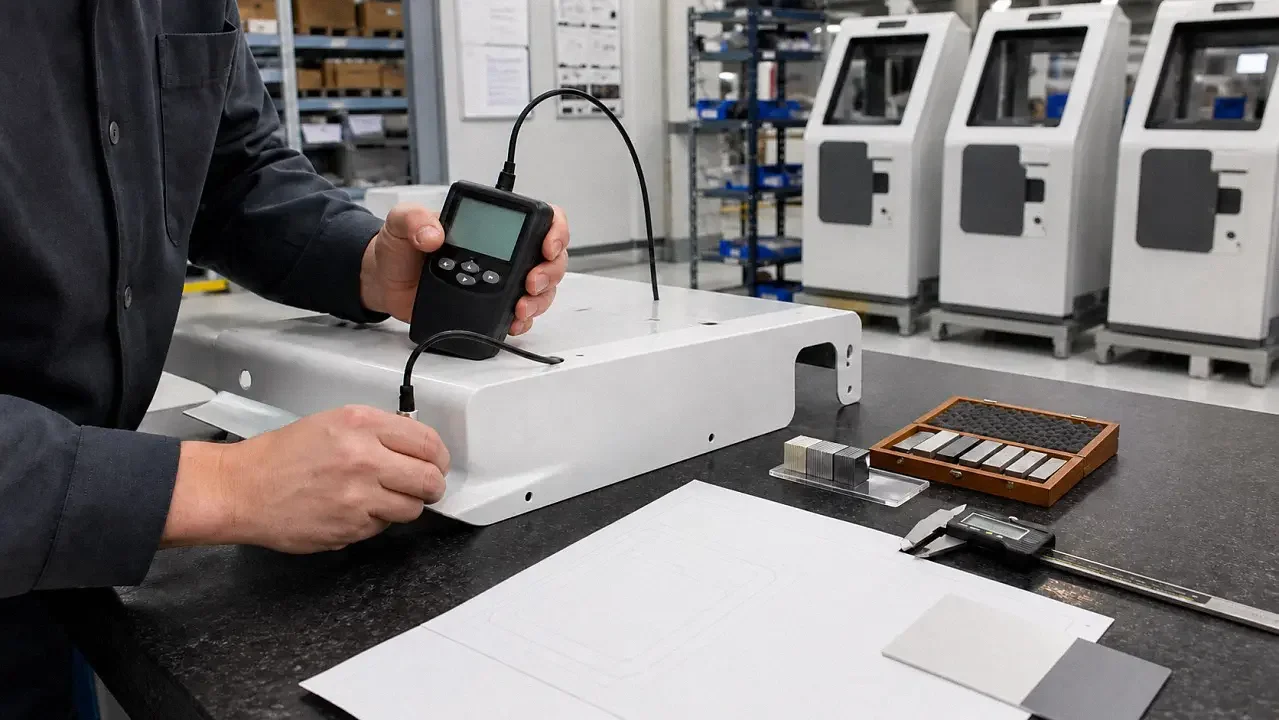
A usable coating callout includes substrate, pretreatment, powder family, color reference, gloss range, dry-film thickness, cosmetic class, masked areas, and the inspection method. ASTM D7091 covers nondestructive dry-film measurement; ASTM D3359 provides a tape-test method for rating coating adhesion. For color, ASTM D2244 explains instrumental color-difference calculations, but buyer and supplier still need to agree on the tolerance and visual reference.
Also call out grain direction on brushed stainless, weld finishing, stainless cleaning or passivation where required, edge condition, gasket and sealant part numbers, hardware torque strategy, and the condition in which flushness or gaps are measured. Adjacent panels should be evaluated as an assembly because hinge, coating, gasket, and bracket stack-ups all affect the result.
Build the validation plan around failure modes
|
Area |
What to verify |
When |
|
Material and forming |
Material certificate, thickness, grain direction where relevant, bend samples |
Incoming lot and first article |
|
Finish |
Dry-film thickness, adhesion, color/gloss, masked bond areas, cosmetic master |
First article plus defined production sampling |
|
Cleaning compatibility |
Actual facility-approved products, concentration, wet contact time, wipe material, repeat cycles |
Prototype and any finish/supplier change |
|
Mechanical/service |
Door alignment, latch force, fastener retention, cable clearance, refill access, cycle test |
Prototype and production audit |
|
Safety/environment |
Protective bonding, touch-current or dielectric tests as applicable, ESD/EMC, thermal, ingress |
Per the selected product standard and certification plan |
For a printer door opened once or twice a day, a 10,000-cycle qualification is a defensible project target with margin, but it should still be tied to the intended service life and latch design. The same logic applies to disinfectant cycles and filter loading: derive the test from field use, document the acceleration method, and define what counts as failure before testing starts.
A common pitfall we see is excellent inspection of individual panels followed by poor control of the assembled kiosk. Include an assembled first article with door-gap mapping, bezel flushness, anchorage, tip stability, rattle checks, service access, bonding, thermal performance, and cleaning compatibility. That is where most interactions become visible.
A practical enclosure is the result of documented tradeoffs
A medical kiosk enclosure does not need to be all stainless, excessively heavy, or sealed like outdoor equipment to be dependable. It needs a material and finish that match the cleaning chemistry, a structure that supports real service loads, an airflow path that can be maintained, controls that remain accessible in the installed geometry, and a validation plan tied to field use.
The most useful design reference is therefore not a universal material ranking. It is a short set of verified inputs—cleaning SOP, equipment classification, component heat load, service frequency, user approach, finish specification, and measurable acceptance criteria. With those in place, the sheet-metal details become easier to defend, source, inspect, and revise.