
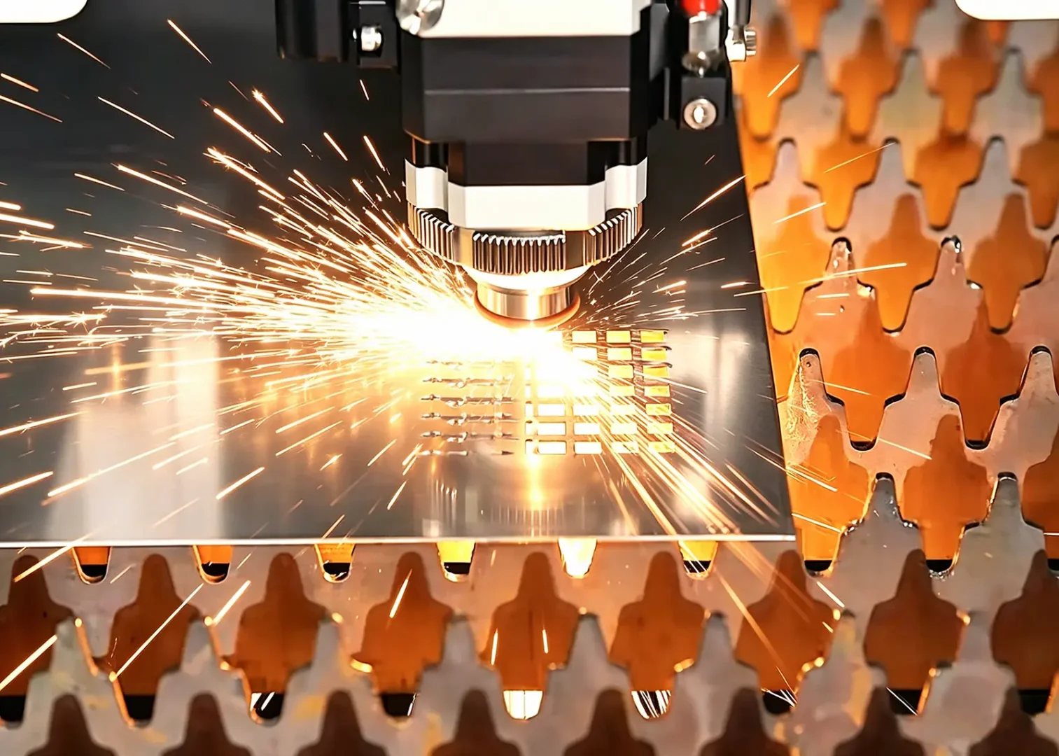
Laser cutting is a reliable technology in sheet metal fabrication. It delivers precision and efficiency when set up correctly.
But even the best laser cutter can produce bad results. Burrs. Rough edges. Inconsistent kerf.
The culprit is often not the machine's power or speed. It's the laser focus position (also called beam spot position).
This guide explains why focus position matters, the three focus modes, when to use each, and a real problem from an actual shop floor.
1.Why Laser Focus Position Determines Final Cutting Quality
Laser cutting works by concentrating a high-energy beam onto a small spot on the metal surface. The material melts or vaporizes, and an assist gas blows away the molten debris.
Focus position is simply the distance between the laser's focal point and the workpiece surface.
That small distance directly affects:
- Energy density in the kerf, which determines whether the beam fully penetrates the material
- Kerf width, which directly affects dimensional accuracy
- Heat-affected-zone (HAZ) size; a smaller HAZ reduces thermal distortion in thin sheet
Research data from Germany’s ILT (Institute of Laser Technology) indicate that a focal-point deviation of only 0.1 mm can increase burr formation by 30% and reduce cut-edge smoothness by 25%.
In high-precision applications, including aerospace brackets and medical-device components, accurate focal-position calibration is an essential quality-control step.
2.Three Standard Laser Focus Modes: Application & Parameter Reference
Based on the position of the focal point relative to the sheet surface, laser-cutting settings are classified as positive, zero, or negative focus. The comparison table below serves as a quick on-site reference for sheet metal technicians.
Table 1 Laser Focus Mode Complete Comparison
| Mode | Focal Point Location | Kerf Cross-Section | Core Advantages | Suitable Materials and Thicknesses |
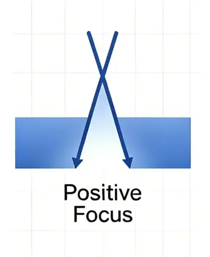
| Positive Focus | 0.5–2mm above sheet surface | Trapezoidal kerf, wider bottom slit | Less bottom-edge slag and fewer burrs; faster cutting | Carbon steel 10–25mm, structural frames, thick brackets |
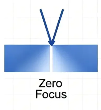
| Zero Focus | Exactly on sheet surface | Narrow straight kerf (0.1–0.3mm for fiber laser) | Minimum HAZ, highest dimensional precision | Thin sheet metal, 0.5–6 mm; intricate precision parts |
| Negative Focus | 0.5–1.5mm under sheet surface | Inverted trapezoidal kerf, wider top slit | Smooth cut edges, avoids top edge melting | Stainless steel, aluminum, galvanized steel 3–12mm |
2.1 Positive Focus (Focal Point Above Workpiece)
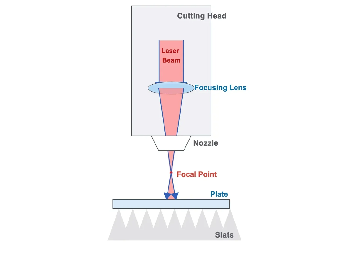
Working Principle
The focal point stays 0.5–2mm above the raw sheet, forming a trapezoidal kerf wider at the bottom. This kerf shape improves the flow of oxygen assist gas and helps expel molten slag from carbon steel.
Core Advantages
-
Greatly reduces bottom burr and slag residue
-
Boosts cutting efficiency for thick carbon steel plates
-
Stable penetration for high-carbon alloy steel
Suitable Production Scenarios
Oxygen cutting for A36, S235JR carbon steel, heavy structural brackets, machine base frames, mass production requiring fast cutting and clean edges.
Supporting Research Data
Journal of Materials Processing Technology, 2022: When cutting 15 mm carbon steel, a positive-focus setting reduces slag formation by 40% compared with a zero-focus setting.
2.2 Zero Focus (Focal Point On Sheet Surface)
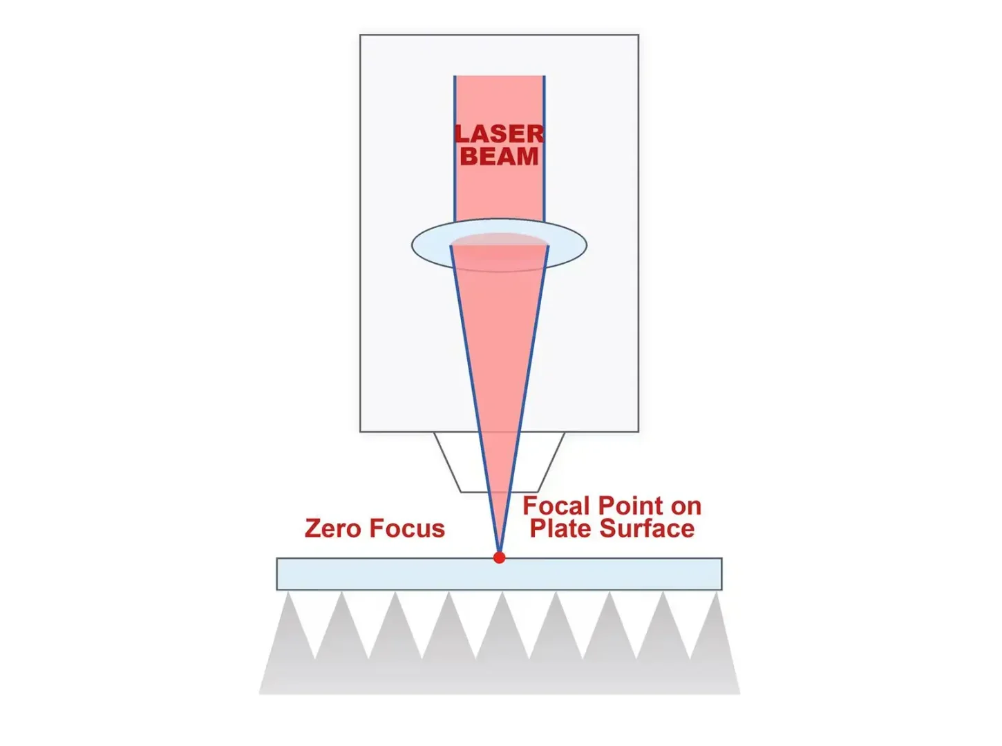
Working Principle
The focal point aligns perfectly with the material surface, achieving peak laser energy density and the narrowest kerf (0.1–0.3mm for fiber laser equipment).
Core Advantages
-
Minimal kerf loss, reducing material waste
-
A small heat-affected zone, reducing thermal distortion in thin sheet
-
High cutting speeds for ultrathin sheet metal
Suitable Production Scenarios
Suitable for precision cutting of thin stainless steel, aluminum, and brass, including intricate electronic enclosures, medical-instrument components, and heat-sensitive 6061 aluminum parts.
Real Workshop Case
Our factory used a zero-focus setting for stainless-steel electronic-housing orders. The process consistently achieved a dimensional tolerance of ±0.05 mm and reduced material waste by 12% compared with conventional cutting parameters.
2.3 Negative Focus (Focal Point Under Workpiece Surface)
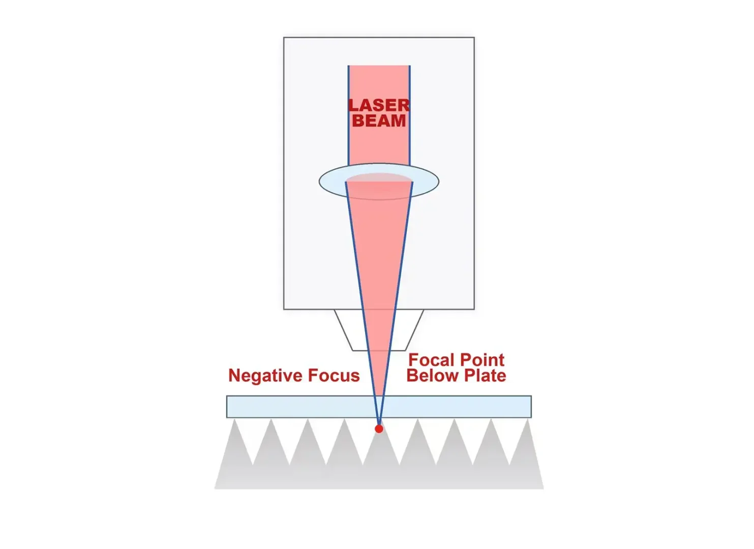
Working Principle
The focal point is set 0.5–1.5 mm below the sheet surface, creating an inverted trapezoidal kerf with a wider top opening. This helps maintain sufficient energy density at the bottom of the kerf when cutting reflective metals such as stainless steel and aluminum.
Core Advantages
- Eliminates top edge melting and dross buildup
- Delivers ultra-smooth finish for non-ferrous metals
- Compatible with inert-gas cutting using nitrogen or argon, helping avoid surface oxidation
Suitable Production Scenarios
Suitable for nitrogen cutting of 304 or 316L stainless steel and 5052 or 6061 aluminum; for cutting galvanized steel while limiting zinc-vaporization defects; and for food- and pharmaceutical-equipment parts that require oxide-free cut surfaces.
Supporting Industry Data
The TRUMPF laser-application manual reports that, when nitrogen is used as the assist gas, a negative-focus setting improves the cut-surface roughness (Ra) of 8 mm 304 stainless steel by 35%.
3. Common On-Site Fault Case: Yellow Oxidation & Heavy Burrs On Stainless Steel Parts
Fault Phenomenon
A metal-fabrication shop received complaints that all cut 304 stainless-steel parts had yellowed, oxidized edges and heavy burrs. Repeated adjustments to the focus parameters did not improve the results.
Root Cause
A field inspection found scattered burn marks across the protective laser lens, which had significantly shifted the focal position. The problem was unrelated to the numerical focus settings or machine-axis alignment.
Solution
After the damaged optical lens was replaced, cutting quality immediately returned to normal.
Key Lesson
Always inspect the full laser optical path before adjusting focus parameters. Contaminated lenses, burn scratches or internal moisture will offset focal position. Parameter fine-tuning cannot fix optical component failure.
4. Practical Standardized Operation Tips For Laser Focus Calibration
-
Match the Focus Mode to the Material and Thickness: Use the comparison table above as a baseline, then verify the settings before production.
-
Calibrate the Focus Regularly: Thermal expansion and material-thickness variation can shift the focal point. Do not reuse previous settings without verification. As a baseline, calibrate after every eight hours of continuous production or whenever the material changes. Use focus-test coupons for quick verification; the article estimates that the check takes no more than two minutes and can help prevent hours of rework and scrap.
-
Start With the Software Presets, Then Fine-Tune: Mainstream fiber-laser systems, including CypCut, LaserMark, TRUMPF LaserTec, and Amada Locus, include focus presets for common metals. Apply a preset first, then adjust the focal distance by up to ±0.2 mm based on the observed cut quality.
-
Measure the Results Instead of Relying on Visual Judgment: Visual inspection cannot quantify cutting defects accurately. Use appropriate instruments to collect objective data:
-
a profilometer to measure cut-edge roughness (Ra)
-
a coordinate measuring machine (CMM) to verify dimensional tolerances.
-
5.Core Summary
Laser focus position is not a minor setup detail; it directly affects three key production outcomes: finished-part quality, rework and scrap rates, and material waste.
Quick Reference
|
Focus Mode
|
Cutting Feature
|
Primary Application
|
|
|
Wider bottom kerf, optimized slag discharge
|
Oxygen cutting for thick carbon steel
|
 |
Narrowest kerf, minimal HAZ, ultra-high precision
|
Thin metal & intricate precision components
|
 |
Wider top kerf, stable energy for reflective alloys
|
Nitrogen cutting for stainless steel, aluminum & galvanized steel
|
Master the three focus modes, verify parameters with test coupons before batch production, and prioritize optical lens inspection when cutting defects occur.